The Problem with Treating Geogrid Specs as a Checklist
A lot of project specifications for geogrids read like a shopping list. Tensile strength? Check. Aperture size? Check. Junction efficiency? Probably not even on the page. And creep behavior, well—that stays buried in a manufacturer's internal test report that nobody sees until something goes wrong.
The global geogrid market hit an estimated USD 1.41 billion in 2025, with projections reaching USD 2.16 billion by 2034 at a CAGR of 4.70%. That growth reflects real infrastructure spending—roads, retaining walls, railway ballast stabilization—not speculative demand. Yet the gap between how geogrids are specified and how they actually perform in the ground remains stubbornly wide.
This matters because geogrid reinforcement does not fail the way steel does. There is rarely a single dramatic rupture. More often, the soil mass creeps slowly over years, the junctions degrade incrementally, and one day the pavement surface tells you what was happening underneath all along.
How Geogrids Actually Reinforce Soil: Interlock, Friction, and Load Transfer
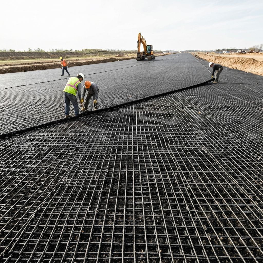
The geogrid reinforcement mechanism is not complicated, but it is routinely misunderstood. Two things happen when you embed a geogrid in granular fill.
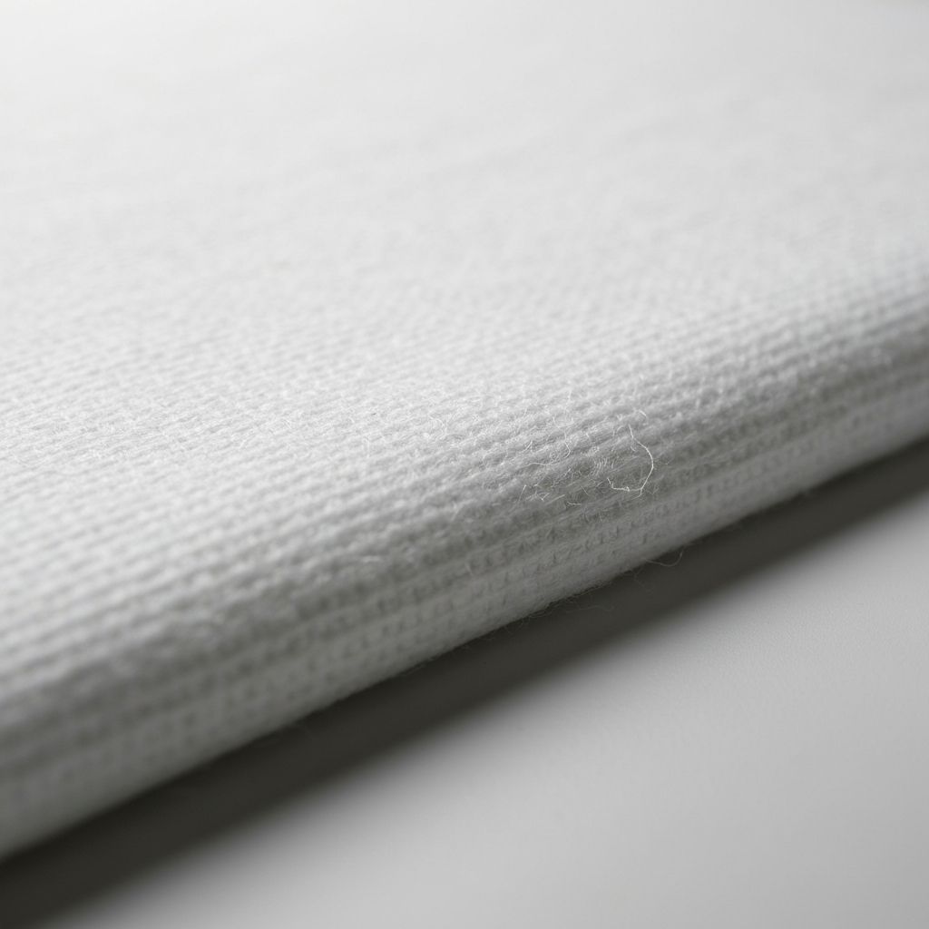
First, there is skin friction at the rib-soil interface. This is straightforward: the longitudinal ribs resist pullout through the same frictional mechanism that governs any soil-structure interface. But friction alone does not explain why a geogrid outperforms a flat geotextile sheet with comparable surface area.
The difference is the second mechanism: passive bearing resistance mobilized against the transverse ribs. When the geogrid is loaded in tension, the cross-direction ribs act like miniature retaining walls embedded in the fill. The pullout resistance contributed by this bearing mechanism has been observed to kick in at around 25% of the maximum pullout force, and interference between transverse ribs becomes significant at roughly 60% of maximum pullout force.
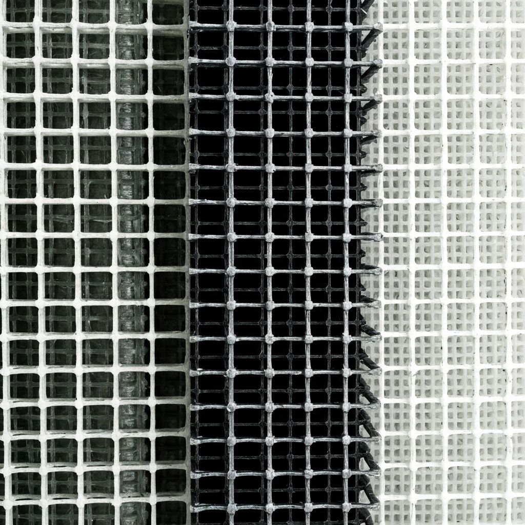
This is why geogrids are fundamentally different from geotextiles. With geogrids, the aperture size and rib geometry matter as much as the raw tensile strength.
Why Junction Strength Is Not an Afterthought
If the transverse ribs do the heavy lifting in the bearing mechanism, then the junctions—the connection points where transverse ribs meet longitudinal ribs—become the critical load path. A geogrid junction must transfer the passive resistance generated at the cross rib into the main tensile member (the longitudinal rib) without failing.
The Geosynthetic Research Institute's GRI-GG2 test procedure is the most widely used method for quantifying junction strength. For a geosynthetics manufacturer, junction efficiency—typically expressed as a percentage of the rib's tensile strength—is one of the strongest indicators of manufacturing quality control. Published product specifications commonly cite junction efficiency values of 90% or above for reinforcement-grade geogrids.
Tensile Strength Alone Won't Save You: The Full Picture
| Parameter | Uniaxial Geogrid | Biaxial Geogrid | Notes |
|---|
| Primary strength direction | Machine direction only | Machine + cross-machine | Uniaxial for linear loading; biaxial for areal loading |
| Tensile strength range | 20–250 kN/m | 20–250 kN/m | Upper range depends on polymer and manufacturing |
| Junction efficiency (typical) | ≥90% | ≥90% | Per GRI-GG2 test method |
| Elongation at max load | ≤12% | ≤12% | Lower elongation = stiffer response |
| Aperture size range | 25×25mm to 65×65mm | 25×25mm to 65×65mm | Must match aggregate gradation |
| Best application | Retaining walls, steep slopes | Pavement base, working platforms | Match product type to load directionality |
Creep: The Slow Killer That Design Codes Try to Quantify
Creep is the tendency of a polymeric material to deform continuously under sustained load. For geogrids, creep matters because the design life of a reinforced structure typically runs 50 to 100 years. Ignore creep, and you are effectively betting that the polymer will stop deforming sometime before the road surface cracks.
The standard approach in North America follows the AASHTO PP66-10 protocol, which defines reduction factors for installation damage (RF_ID), creep (RF_CR), and chemical/biological degradation (RF_CH), then combines them to calculate the long-term design strength.
A global review of 66 different geogrid products from 10 manufacturers, comprising 362 individual constant-load creep tests, found that the long-term allowable tensile strength is typically only 30–40% of the ultimate tensile strength—meaning 60–70% of capacity is consumed by safety and reduction factors by the time the design is complete.
A Practical Geogrid Selection Framework
- First: What is the load direction? If the principal stress aligns with a single axis (retaining wall, steep embankment), a uniaxial geogrid is the correct starting point.
- Second: What is the aggregate gradation? Geogrid aperture size must be matched to the fill material's particle size distribution.
- Third: What are the junction requirements? For any project where the geogrid will experience significant pullout loading, junction efficiency should be specified and verified.
- Fourth: What is the creep design life? Match the design life to the project timeline, and apply reduction factors accordingly.
- Fifth: What are the installation and environmental conditions? Installation damage from aggressive backfill can cut tensile strength significantly before the structure ever sees its design load.
Conclusion: The Spec Needs the Science
Geogrids work because of a mechanical chain: tensile ribs carry the load, transverse ribs mobilize bearing resistance, junctions transfer that resistance into the main tensile members, and the aperture structure interlocks with the surrounding fill. Break any link in that chain—specify the wrong directionality, ignore junction strength, underestimate creep—and the system degrades, slowly then suddenly.
The products are capable. The testing standards exist. The remaining gap is between the spec and the science—and closing that gap is where better geogrid selection starts.